
Similarly, to prevention controls, on the right-hand side of the top event, controls are added that show how the scenario is to be managed to stop the consequence from occurring.
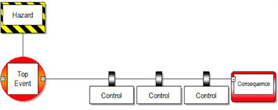
These controls are in place to reduce the likelihood of the top event developing into a consequence as well as mitigating the severity of the consequence.
In our example of driving a car on a busy motorway, a reduction control would be anti-lock braking system (ABS) to constrain the loss of control parameters to not affect other motorway users. A mitigating control could be an airbag activation acting against the fatal severity of the consequence.
Additional guidance (relevant to prevention and recovery controls)
Parallel versus sequential controls
Controls will usually be sequential e.g. if one fails then the next one would come into play. However, it is not uncommon for controls to be included which do not function in this way but rather have an ‘either/or’ type relationship (also known as ‘parallel controls’).
For example, consider the following aircraft loading scenario: Load and trim calculations are an important control against an incorrect distribution of load but there are several ways in which this might be achieved:
- central control system;
- manual load sheet;
- electronic flight bag.
These could be represented on the bowtie as three controls; however for any given departure only one will actually be used (e.g. they are parallel controls).
Bowtie diagrams do not model parallel controls specifically.
This is a trade-off between being analytically correct and being an easily understandable tool.
Therefore, it visually looks as though all controls are sequential. In this situation, what could be interpreted as three controls, is in effect only one dependent on the operation type.
It is vital to keep in mind that it should not be assumed that controls are always sequential when building or referring to a bowtie. This is also one of several considerations that tend to make the counting of controls to determine sufficient protection a flawed technique.
Independence of controls
It is not uncommon for controls to be represented which are not independent.
This occurs when it is desirable to highlight separate aspects of a control to depict specific escalation factors e.g. detecting a problem and then actioning the appropriate response.
Consider for example, fire detection and firefighting. Clearly the two are not independent e.g. detection is not a standalone control as it does nothing to stop a fire, whereas firefighting will not commence until the fire has been detected.
As with parallel controls, these dependencies degrade the validity of counting controls.
See Prevention controls for traps and tips relevant to recovery control.
Provide page feedback
Please enter your comments below, or use our usual service contacts if a specific matter requires an answer.
Fields marked with an asterisk (*) are required.